2. Modelling continued.
As you model, set all objects you create as see through by right clicking on the object and going to Properties, then checking the See Through box. Or if like me you like working in colour, try adjusting the Visibility under Rendering control to about 0.2. You should then be able to see the drawings through the objects. Also, since you disabled transparency in your Perspective view, you can see the solid model too!
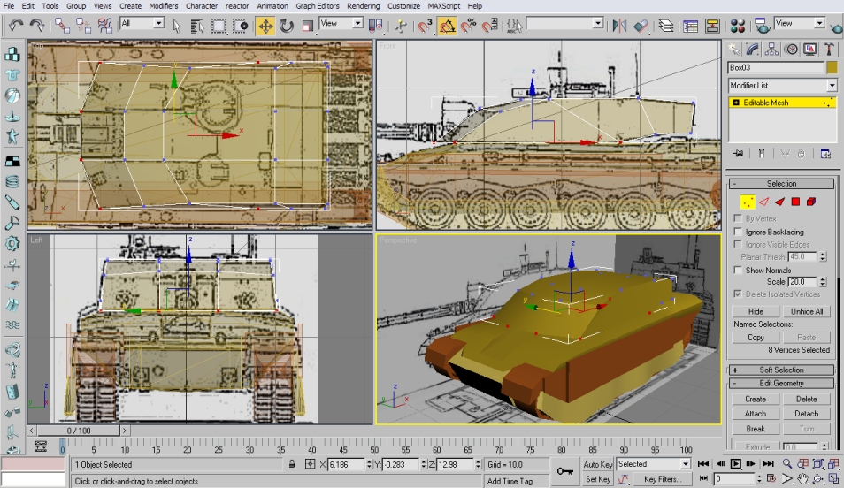
Keep the objects as close to the drawings as you can. Sometimes you may find faults in the drawings, some edge lines not lining up in the different views for example. Should this happen, it's good to have references to look at to help you get it to look right.
Try and use as few objects as possible to make the shapes. Make use of the extrude and chamfer tools to add those extra faces to the end of your object for that extra curve or detail. Weld the vertices of any adjacent faces you attach together to seal gaps and reduce the vertex count.
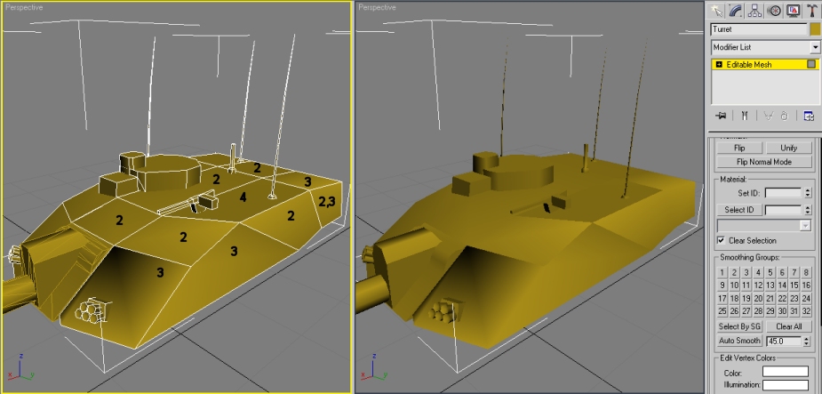
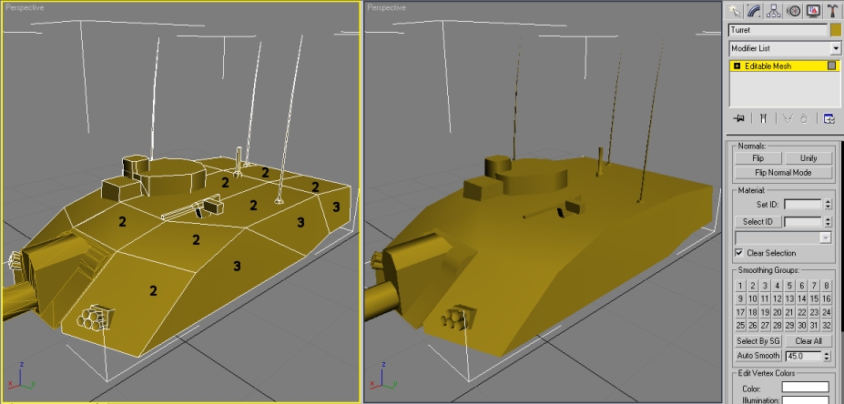
These may make your object look a bit blocky though, so remember to select all faces and Auto Smooth it (You will find the button at the bottom of the modify tab on the right panel when you have faces selected). If that produces undesirable results, you can try setting the smoothing groups manually.
Any adjacent faces with the same smoothing group number will be smoothed. If the numbers are different, they will appear to have a hard edge between them. A face can have more than one number of smoothing group to smooth with other faces around it, which may be in different groups. The examples in the pictures here show the smoothing group number applied to the faces, with the result.
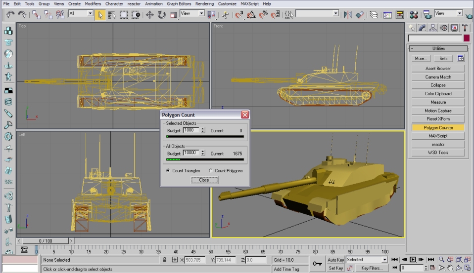
So, fast-forward a bit. There's my model. I'm happy with the detail there, and the polygon count is good too. This would be a good time to texture it!
Previous | Next
 - all rights reserved.